


Round baler
9YQ-19509YQ-1950 Round-Bale Hay Wrapper | High Efficiency in the Field | Easy Maintenance
View Details→

 Wheat Stubble Primary Tillage
 Corn Residue Soil Mixing
 Pre-Sowing Field Preparation
 Fallow Field Clod BreakingWheat Stubble Primary TillageCorn Residue Soil Mixing
01 /Description
Heavy Disc Harrow Across Field Tasks
Heavy-duty disc harrow. Application settings include Wheat Stubble Primary Tillage; Corn Residue Soil Mixing; Pre-Sowing Field Preparation; Fallow Field Clod Breaking. Match the selected configuration to the available space, access and intended use before ordering.
02 / Specs & Parts
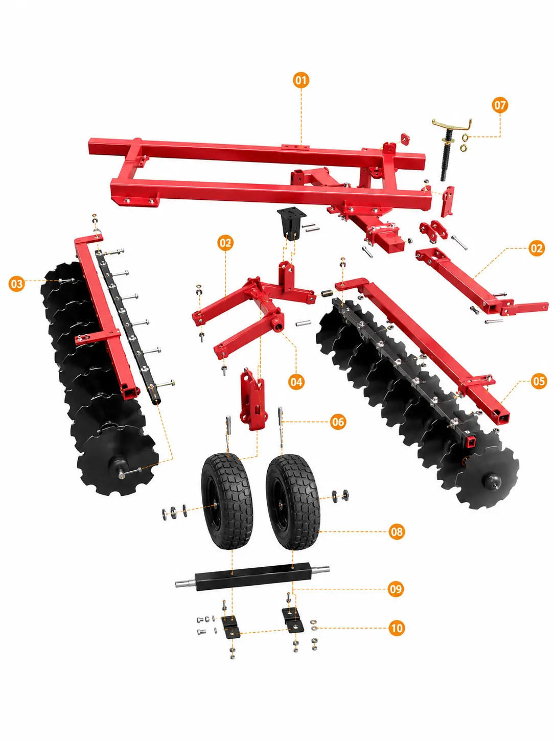
The red twin-beam frame carries the gang brackets, wheel linkage and drawbar connection as one visible base.
The long red drawbar links the front frame position to the tractor-side towing point shown in the assembly.
This black scalloped disc gang includes its square support beam, shaft, spacers and visible end hardware.
Paired red pivot arms connect the main frame to the central wheel-support position shown in the diagram.
The matching black scalloped disc gang includes its gang beam, shaft, bearing points and end fasteners.
The red vertical bracket provides the confirmed mounting position between the pivot linkage and wheel unit.
The exposed screw, spring and handle form the visible adjustment assembly located beside the drawbar frame.
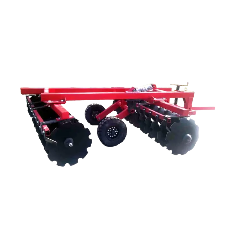
Every formal image uses the same red twin-beam frame, paired disc gang assemblies, paired center wheels, drawbar and screw adjuster.
Review the visible towing point, frame bolts, gang shafts, bearing areas, wheel linkage and adjustment hardware.
The purchasing plan lists the product color as Confirm color before ordering.
The scenes show wheat stubble, corn residue, pre-sowing preparation and dry fallow clod breaking.
Communicate special requirements based on actual needs so the requested details can be reviewed before confirmation.
 Simplified explanation