


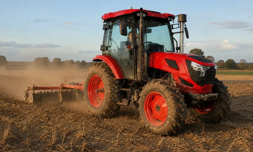
 Farm Lane Transit: Muddy Farm Lane Travel. WW-904B is shown in this working setting; confirm implement fit, terrain, route clearance and operating conditions before use.
 Plowed Soil Pass: Tire Tracks Across Plowed Soil. WW-904B is shown in this working setting; confirm implement fit, terrain, route clearance and operating conditions before use.
 Farm Lane View: Farm Lane Between Crop Fields. WW-904B is shown in this working setting; confirm implement fit, terrain, route clearance and operating conditions before use.Farm Lane Transit: Muddy Farm Lane Travel. WW-904B is shown in this working setting; confirm implement fit, terrain, route clearance and operating conditions before use.
 Stubble Field Pass: Stubble Field Implement Work. WW-904B is shown in this working setting; confirm implement fit, terrain, route clearance and operating conditions before use.Plowed Soil Pass: Tire Tracks Across Plowed Soil. WW-904B is shown in this working setting; confirm implement fit, terrain, route clearance and operating conditions before use.Farm Lane View: Farm Lane Between Crop Fields. WW-904B is shown in this working setting; confirm implement fit, terrain, route clearance and operating conditions before use.
01 /Description
Steady Field Travel and Implement Work
Practical tractor work across everyday farm ground
The working views show the tractor pulling a simple soil implement across prepared ground, traveling along a broad bare-soil farm lane, moving beside open fields and crossing a harvested stubble field. Wheels stay on firm traffic surfaces while operators remain at a believable scale. Natural farm buildings, clear horizons, light dust and used tire marks present ordinary working conditions rather than a staged promotion.
02 / Specs & Parts
Specifications & Structural Decomposition
Product Structure Diagram

- horsepower
- 90hp
- Applicable Scenarios
- Farm Lend, wheat Field,Vesetable Garden, Dry Land
- External dimensions
- 4050*1830*2660 mm
- Chassis
- TB Type
- Weight
- 2850KG
- Engine model
- Yangdong
General information

- 1. Operator Station
The seat, steering controls and protective frame or cab form the primary driving position for field work.
- 2. Hood and Front Grille
The hood and front grille cover the engine bay while shaping front service access and airflow.
- 3. Engine Assembly
The engine assembly supplies the mechanical power required for controlled tractor travel and implement operation.
- 4. Exhaust System
The exhaust assembly routes engine gases upward and keeps the outlet clear of the operator position.
- 5. Chassis Frame
The central chassis frame joins the main systems and provides the rigid mounting structure for axles and body sections.
- 6. Front Axle
The front axle carries the steering wheels and transfers front-end loads while the tractor moves across uneven ground.
- 7. Front Wheel Set
The front wheel assemblies provide steering contact and deep tread for stable travel over prepared soil.
Product Attachments or Core Configurations

Heavy Duty Loader Bucket

Single Direction Disc Plow

Heavy Duty Trencher Attachment

Hydraulic Hay Rake Attachment
General instructions
 Simplified explanation
Core Component Details
Frequently Asked Questions (FAQ)
What product type is shown?
The supplied materials show a four-wheel agricultural tractor with an operator station, treaded wheels and rear linkage hardware.
Which configuration is confirmed?
The confirmed configuration is limited to the features visible in the supplied product images; no unverified options are added here.
What should be checked before use?
Before use, inspect tire condition, controls, fluid levels, linkage pins and the work area, then follow the applicable operating manual.
Where can it be driven safely?
Use it only on suitable agricultural ground with adequate clearance, stable soil and safe separation from people and obstacles.
How should it be cleaned after work?
Remove loose soil from the tires and lower chassis after work, then inspect exposed linkage points before storing the tractor.