


Architrave grooving machine
MTX01Door casing groove‑cutting machine | Stable machining | Seamless process integration
View Details→
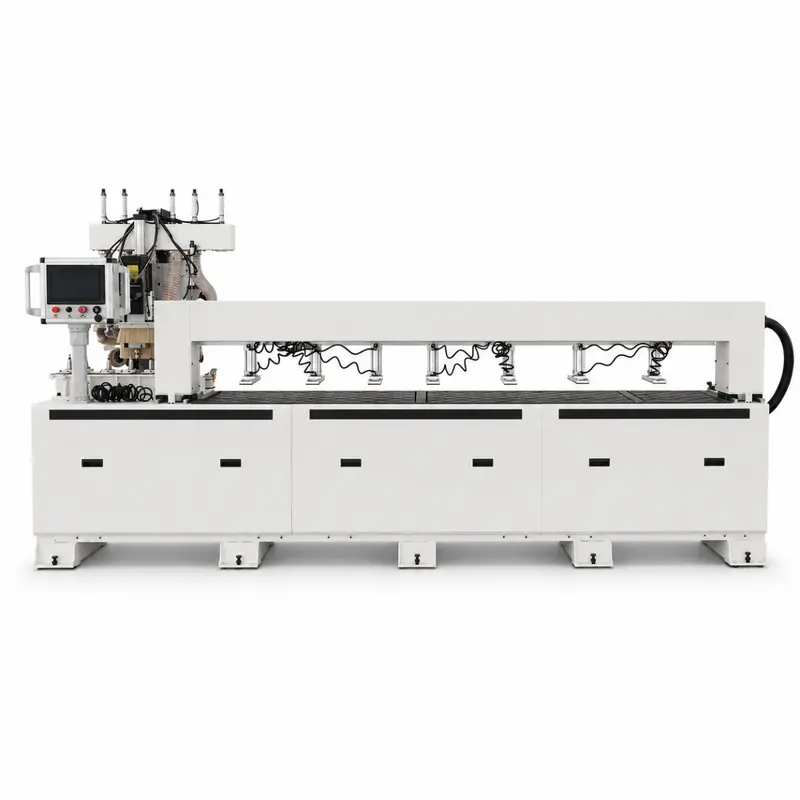
 Guided Table Visibility in Workshop
 Multi Station Layout in Door Showroom
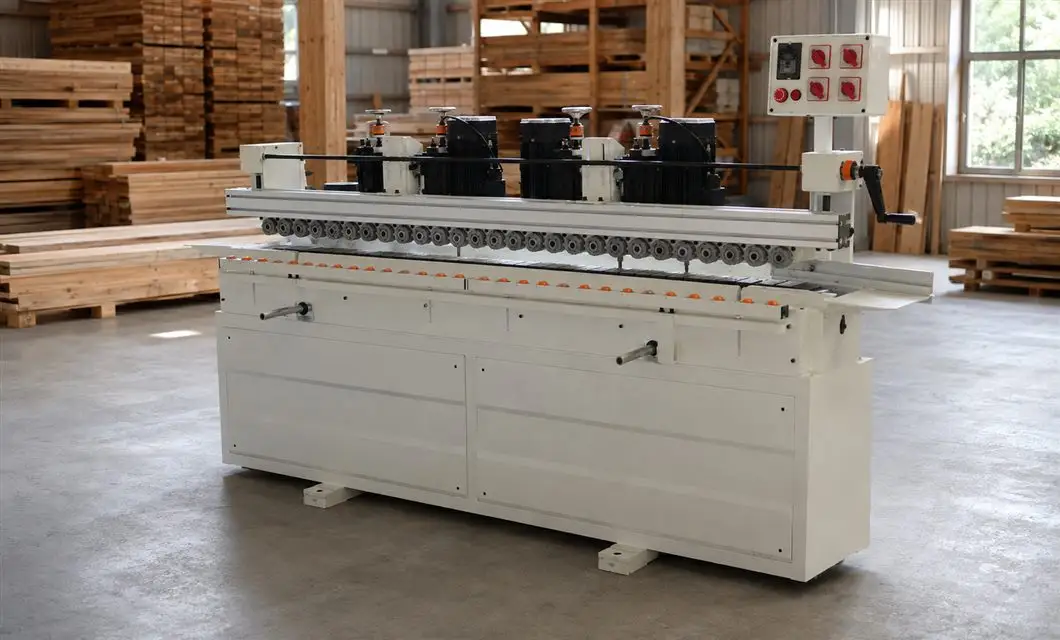 Stable Support on Warehouse Floor
 Guarded Drive Access in StudioGuided Table Visibility in WorkshopMulti Station Layout in Door Showroom
01 /Description
Continuous-Feed Workshop Placement
The machine is presented in workshop, showroom and warehouse-style spaces where its continuous roller line and grouped motor stations remain clearly visible. Different viewpoints highlight the side guide drive, handwheel adjusters, electrical panel and enclosed cabinet base while showing the floor clearance needed around the feed path.
02 / Specs & Parts


The raised enclosure positions the operating controls beside the processing line.
Multiple motorized working units form the main processing assembly above the feed path.
The horizontal shaft and supports coordinate guided movement across the upper frame.
Four separated columns hold the working assembly at its installed operating height.
The end-mounted geared motor supplies drive to the connected conveyor mechanism.
The long bed supports the roller path and locates the material feed components.
The exposed chain, sprockets and shafts transmit motion along the conveyor line.
03 / Specs, Parts & Accessories
Service Videos
Standardized product packaging protects goods during transit and presents a neat brand image.
Service Videos · 00:32Standardized product packaging protects goods during transit and presents a neat brand image.
Service Videos · 00:15Products are neatly loaded into containers for safe and efficient overseas shipment.
Real on-site records from our factory, offering a practical view of our production capability and delivery readiness.
Closely spaced conveyor rollers and the upper pressure line create a continuous visible route across the machine.
The slotting motors are separated into multiple stations along the upper frame above the workpiece conveyor path.
Handwheel mechanisms are visible across the upper assemblies and at the machine end for direct mechanical adjustment.
The electrical control panel is raised at one end of the machine, clear of the continuous roller working line.
Retain clear access along the feed path, around the end handwheel and beside the control panel when positioning the machine.
 Simplified explanation