


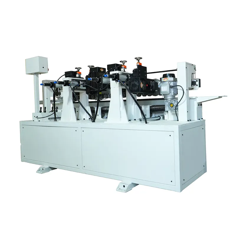
Wainscoting grooving machine
HQB01Wallboard Grooving Machine | A User‑Friendly Solution for Real‑World Applications
View Details→
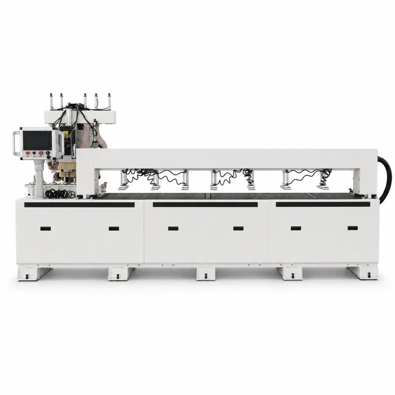
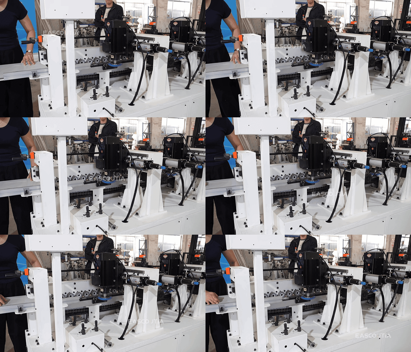
 Guided Table Visibility in Workshop
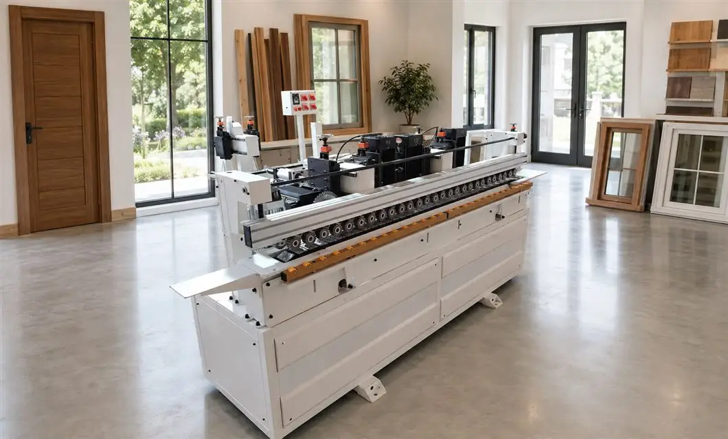
 Multi Station Layout in Door Showroom
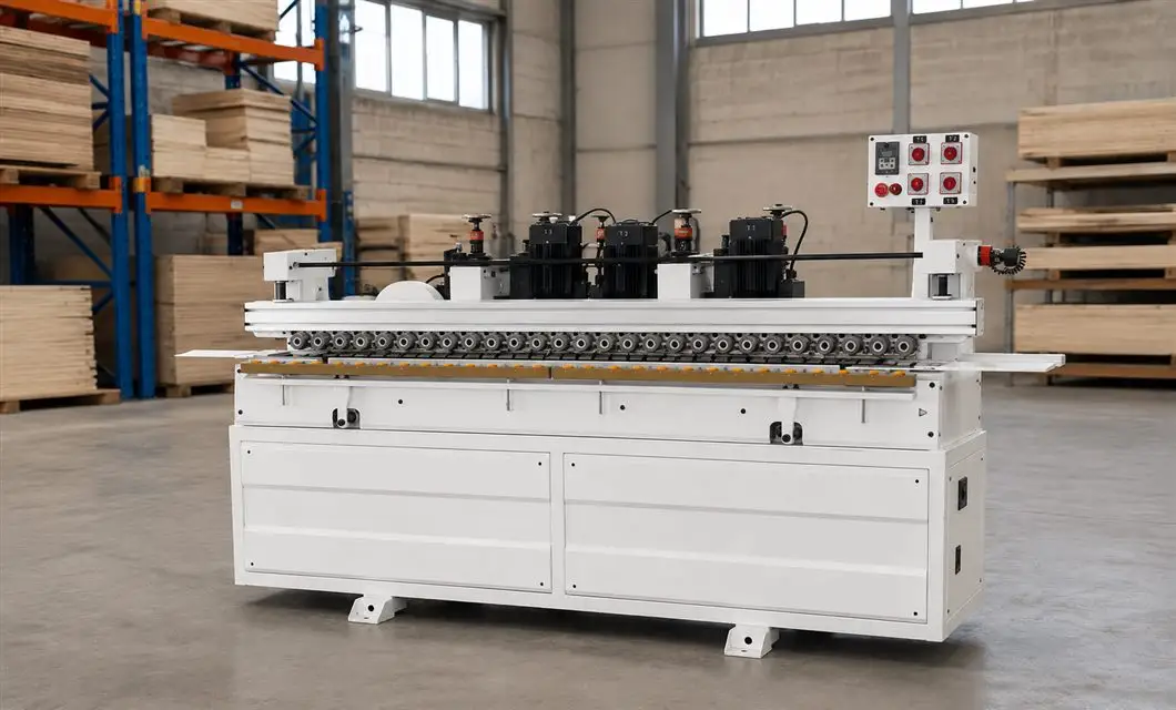
 Stable Support on Warehouse Floor
 Guarded Drive Access in StudioGuided Table Visibility in WorkshopMulti Station Layout in Door Showroom
01 /Description
Door Casing Workshop Applications
Door Casing Slotting Machine. Application settings include Casing Feed Setup; Cutting Head Layout; Compact Floor Setup; Tool Access Side. Match the selected configuration to the available space, access and intended use before ordering.
Combined with rotation, the working mechanism allows multi-directional digging and material placement, minimizing frequent machine adjustments and suiting confined construction sites.
02 / Specs & Parts
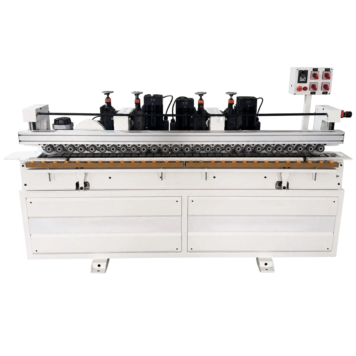

The raised control enclosure keeps the visible switches beside the working line.
Several motorized heads form the main cutting assembly across the upper frame.
The long horizontal beam aligns and supports the mounted processing assembly.
The continuous roller row guides material through the central working path.
The segmented support surface carries material directly below the roller line.
The enclosed cross member locates the upper feed and processing structures.
Two removable panels close the cabinet while preserving lower service access.
03 / Specs, Parts & Accessories
Video Showcase
MTX01 full unit demonstration, solid structure, stable operation for various working conditions
Video Showcase · 00:51MTX01 full unit demonstration, solid structure, stable operation for various working conditions
Operation Videos · 00:36MTX01 machine operation demo, easy to operate, smooth working and stable output
Service Videos · 00:15MTX01 machine container loading & securing, compact placement, safe for ocean transportation
Service Videos · 00:32MTX01 machine export wooden case packaging, reinforced protection, shock and impact resistance
Real on-site records from our factory, offering a practical view of our production capability and delivery readiness.
Material enters through the front infeed conveyor and continues along the guided roller table through the working area.
The supplied views show several separate cutting-drive and head assemblies arranged across the upper machine frame.
The processing stations are grouped along the open working side, where the head assemblies and guides remain visible.
The conveyor surface, guide structure and continuous rollers support the visible material route across the machine.
Keep the infeed end, tool-processing side, control panel and opposite end clear when planning the machine position.
 Simplified explanation